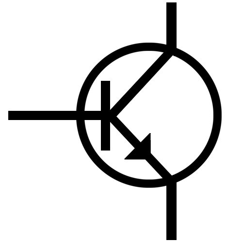
In Higher we need to know about two configurations of Transistors, one to create a greater amplification of current, and one to allow two different things to happen depending on whether the input is positive or negative.
Darlington Pair:
The Darlington Pair uses two transistors with the emitter from one giving the base of the other (two in a row). This gives double the current gain, but also needs double the VBE to saturate the pair.
Note: The easiest thing for you to forget is to carry out your transistor calculations with 1.4v instead of 0.7v. Often this is the value that people most readily forget even in a single transistor!
Push Pull Driver:
The push pull driver uses the two different types of transistor so that when VBE is positive, the NPN transistor will saturate and when VBE is negative, the PNP transistor will saturate.
This allows the current to flow either from positive to 0v or from 0v to negative. If we connect a motor to the 0v (the emitters of each transistor) we can make it turn in both directions. If we connect to different outputs to the collectors of each transistor, we can get a different output from a positive input signal than an negative one.
Friday, 23 September 2011
Thursday, 22 September 2011
Applied Electronics - Outcome 1 - Revision of last year
The first part of Applied Electronics was a revision of Intermediate 2 and a reminder of the fundamental rules.
Also important is your ability to use Prefixes and symbols. They are based on scientific notation where the powers are multiples of 3. Your calculator should have a ENG button to put the numbers into this format for you.
It is also necessary to be able to use voltage dividers and to calculate values using the equation:
R2
Signal Voltage / Output Voltage = R1 +R2 x Vcc
You may need to combine the above with readings from the LDR or Thermistor (or thermcouple) graphs. These are logarithmic and so the axis aren't linear. You have to take care when reading them.
To find a value, read along the axis of the value you know (you could be given either the temperature and asked to find the resistance, or the resistance and be asked to find the temperature) This graph shows that at 25°c the resistance of a type 4 resistor is 50kΩ.
We also looked at transistors:
Transistors are current operated devices which perform two functions:
Transistors have 3 legs:
The base leg is the "trigger" leg - if there is a current here, the transistor will saturate and allow current to flow between the collector and the emitter (in the direction of the arrow on the emitter).
The Transistor as a Switch
If there is no current at the base leg, the transistor material will act as an insulator and no current will flow.
If there is a current at the base the transistor material will act as a conductor and current will flow from the collector to the emitter. (This is just like you pushing a switch with your finger, allowing current to flow through a switch.)
It only takes a small base current to switch on the transistor. When it is fully switched on we say that the transistor is saturated. The voltage required to produce a current which will saturate a transistor is 0.7V.
We need to be able to use the above fundamental principles and the following transistor notation to carry out calculations:
The Transistor as an Amplifier
The nature of the transistor will see that a small base/input current, will be amplified and the collector current will be a lot greater. Technically the base current and the collector current join at the emitter but because IB is so small in comparison to IC we say that IC ~ IE
Consider this circuit.
Because the lamp is on, the transistor must be saturated and VBE = 0.7V.
The gain of the transistor is found using the equation HFE = IC / IB
So if IB was 8mA and the IC was 800mA, the gain of the transistor would be 100. That means that it has amplified the input current by 100x.
Transistor Calculations:
Calculate the current gain of the transistor in this circuit:
First we can work out what we know:
VBE = 0.7V because the lamp is on, the transistor must be saturated.
VR = Vsignal - VBE
= 5.3V
We can then work out the base current:
IB = VR/R
= 5.3/1000
= 5.3mA
And the collector current:
IC = VL/RL
= 6/150
= 40mA
Now that we know both the base current and the collector current we can work out the transistor gain:
HFE = IC/IB
= 40 / 5.3
= 7.55
Note that there is no unit for current gain.
Calculate the voltage dropped over the lamp in this circuit:
First we can work out what we know:
VBE = 0.7V because the lamp is on, the transistor must be saturated.
VR = Vsignal - VBE
= 4.3V
If we know the voltage dropped over the base resistor we can work out the base current:
IB = VR/R
= 4.3/1000
= 4.3mA
If we know the base current and the current gain we can work out the collector current:
IC = HFE x IB
= 10 x 4.3x10-3
= 43mA
If we know the current flowing through the lamp and its resistance we can work out the voltage dropped over it:
V = ICR
= 43x10-3 x 150
= 6.45V
Also important is your ability to use Prefixes and symbols. They are based on scientific notation where the powers are multiples of 3. Your calculator should have a ENG button to put the numbers into this format for you.
It is also necessary to be able to use voltage dividers and to calculate values using the equation:
R2
Signal Voltage / Output Voltage = R1 +R2 x Vcc
You may need to combine the above with readings from the LDR or Thermistor (or thermcouple) graphs. These are logarithmic and so the axis aren't linear. You have to take care when reading them.
To find a value, read along the axis of the value you know (you could be given either the temperature and asked to find the resistance, or the resistance and be asked to find the temperature) This graph shows that at 25°c the resistance of a type 4 resistor is 50kΩ.
We also looked at transistors:
Transistors are current operated devices which perform two functions:
- An electronic switch
- Amplify current - so are used as transducer drivers
Transistors have 3 legs:
The base leg is the "trigger" leg - if there is a current here, the transistor will saturate and allow current to flow between the collector and the emitter (in the direction of the arrow on the emitter).
The Transistor as a Switch
If there is no current at the base leg, the transistor material will act as an insulator and no current will flow.
If there is a current at the base the transistor material will act as a conductor and current will flow from the collector to the emitter. (This is just like you pushing a switch with your finger, allowing current to flow through a switch.)
It only takes a small base current to switch on the transistor. When it is fully switched on we say that the transistor is saturated. The voltage required to produce a current which will saturate a transistor is 0.7V.
We need to be able to use the above fundamental principles and the following transistor notation to carry out calculations:
The Transistor as an Amplifier
The nature of the transistor will see that a small base/input current, will be amplified and the collector current will be a lot greater. Technically the base current and the collector current join at the emitter but because IB is so small in comparison to IC we say that IC ~ IE
Consider this circuit.
Because the lamp is on, the transistor must be saturated and VBE = 0.7V.
The gain of the transistor is found using the equation HFE = IC / IB
So if IB was 8mA and the IC was 800mA, the gain of the transistor would be 100. That means that it has amplified the input current by 100x.
Transistor Calculations:
Calculate the current gain of the transistor in this circuit:
First we can work out what we know:
VBE = 0.7V because the lamp is on, the transistor must be saturated.
VR = Vsignal - VBE
= 5.3V
We can then work out the base current:
IB = VR/R
= 5.3/1000
= 5.3mA
And the collector current:
IC = VL/RL
= 6/150
= 40mA
Now that we know both the base current and the collector current we can work out the transistor gain:
HFE = IC/IB
= 40 / 5.3
= 7.55
Note that there is no unit for current gain.
Calculate the voltage dropped over the lamp in this circuit:
First we can work out what we know:
VBE = 0.7V because the lamp is on, the transistor must be saturated.
VR = Vsignal - VBE
= 4.3V
If we know the voltage dropped over the base resistor we can work out the base current:
IB = VR/R
= 4.3/1000
= 4.3mA
If we know the base current and the current gain we can work out the collector current:
IC = HFE x IB
= 10 x 4.3x10-3
= 43mA
If we know the current flowing through the lamp and its resistance we can work out the voltage dropped over it:
V = ICR
= 43x10-3 x 150
= 6.45V
Subscribe to:
Posts (Atom)